Automatic cutting wireless remote control for crawler rope saw
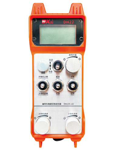
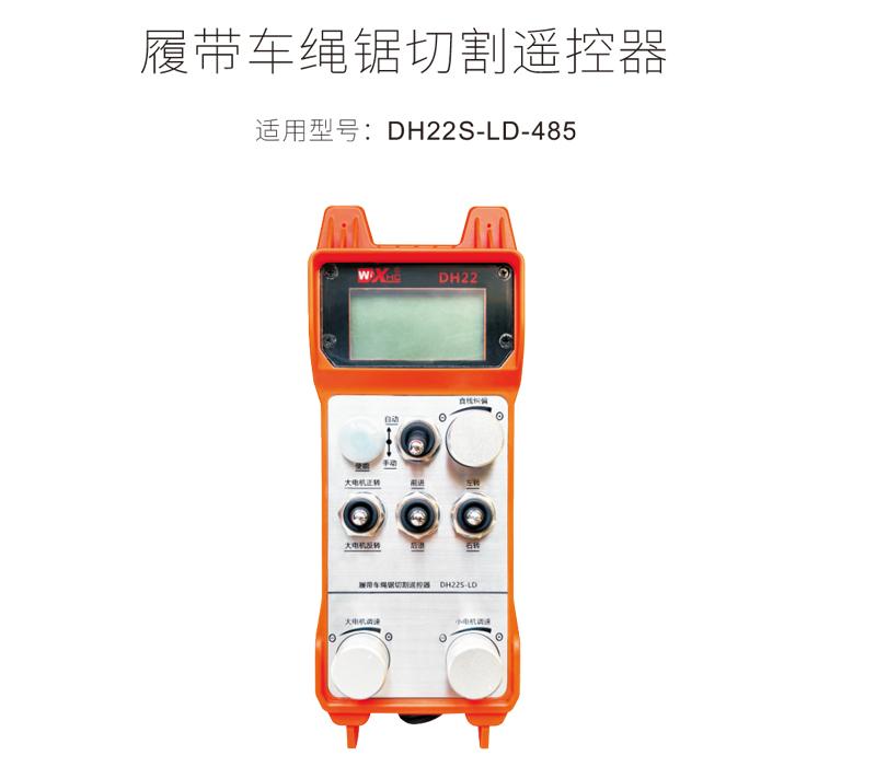
Track car rope saw cutting remote control DH22S-LD-485
Description
1.Product introduction
Crawler wire saw automatic cutting remote control is suitable for crawler wire saw cutting machines,The 485Modbus RTU protocol is used to control the left and right crawler inverter speed regulation start and front, rear, left and right direction control.,And large motor frequency converter speed regulation start。And the working current of the large motor inverter can be read through the 485-Modbus RTU protocol,Analysis and comparison of large motor currents,Automatically adjust left and right track speeds in real time,Realize automatic cutting function。
2.Product features
1.Adopt 433MHZ wireless communication technology,Wireless operating distance 100 meters。
2.Adopt automatic frequency hopping function,Use 32 sets of wireless remote controls at the same time,No effect on each other。
3.Supports all frequency converters with 485 modbus RTU protocol,The currently adapted inverter brands include:Shanghai Xielin、Fuji、Huichuan、Zhongchen、INVT、Yasukawa Tatsu。If the brand is not adapted, please contact us for customization.。
4.Support large motor frequency converter speed regulation、start up、Current reading。
5.Support left and right crawler inverter speed adjustment、start up、Front and rear left and right controls。
6.Support left and right crawler inverter linear correction,Keep the machine moving in a straight line。
7.Support wire saw automatic cutting function,According to the large motor current information,Automatically adjust left and right track speeds in real time。
8.It is also compatible with direct IO output to control motor start and stop.,Analog voltage output controls motor speed。
3.product specifications
| Handheld terminal working voltage and current | 2AA battery-3V/10mA |
| Receiver operating voltage and current | 24V/1A |
| Handheld transmit power | 15dBm |
| Receiver Receive Sensitivity | -100dBm |
| Wireless communication frequency | 433Mhz frequency band |
| Operating temperature | -25℃<X<55℃ |
| Anti-fall height | Comply with national testing standards |
| Waterproof level | Ip67 |
| Product size | 225*84*58(mm) |
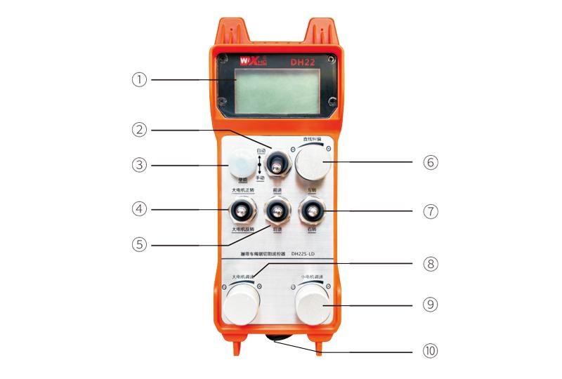
4.Product function introduction
Comments:
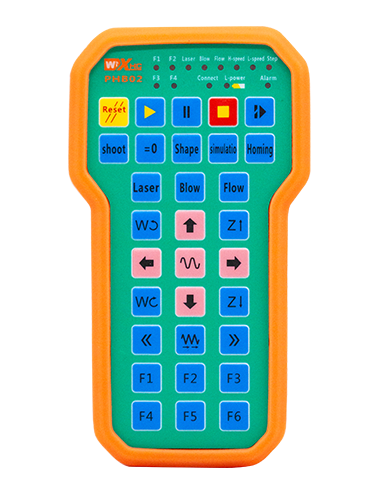
①Screen display:

②Mode switch:
Adopt 2-speed switch,Can switch between automatic and manual modes,There will be a corresponding mode display switch on the display.。
③Enable:
Combination button,Some operations require pressing and holding the enable button to operate,See the description of each switch for details.。
④Large motor switch:
Adopt 3-speed reset switch,flip this switch,Can control forward and reverse rotation of large motors,The status will remain after letting go,There will be a corresponding display on the display,S1↑ arrow indicates forward rotation,S1↓ arrow indicates reversal。
⑤Small motor forward/reverse switch:
Adopt 3-speed self-locking switch,Press the enable button + flip the switch,Can control the small motor to move forward and backward,There will be a corresponding display on the display,↑↑Arrows indicate forward,↓↓The arrow indicates going back。
⑥Linear deviation correction:
Using multi-turn encoder knob,Press enable button,Turn knob right,Straight line correction display:Df:left,Each turn of the knob increases by 1 unit.,The left motor speed increases by 0.1 units;Turn knob left,Straight line correction display:Df:right,Each turn of the knob increases by 1 unit.,The right motor speed increases by 0.1 units。
⑦Small motor turning switch:
Adopt 3-speed reset switch,Turn this switch in manual mode,Can control small motor to turn left and right,The remote control will automatically stop this action after letting go.。In forward state,flip this switch,There will be a corresponding display on the display,←↑ arrow indicates left turn,↑→arrow indicates turning right。In retreat state,flip this switch,There will be a corresponding display on the display,←↓ arrow indicates left turn,↓→arrow indicates turning right。
⑧Speed regulation of large motor:
Using multi-turn encoder knob,Rotate 1 frame each time,The large motor speed value changes by approximately 0.2 units,Rapid rotation can quickly modify the large motor speed value。
⑨Small motor speed regulation:
Using multi-turn encoder knob,In manual mode,Press enable button,Then rotate 1 frame each time,The speed value of the left and right small motors changes by about 0.1 unit,Quick rotation can quickly modify the speed value of the small motor。In automatic mode,Press enable button,Then rotate 1 frame each time,The small motor speed limit value F changes by about 0.1 unit,Quick rotation can quickly modify the speed limit value of small motors。
⑩Remote control power switch:
Remote control display power on。
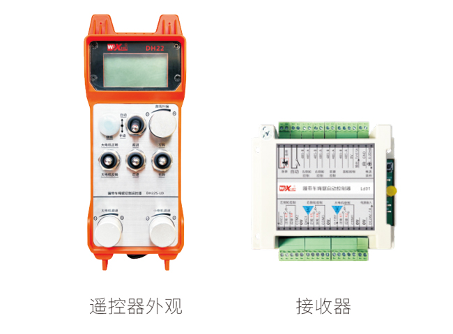
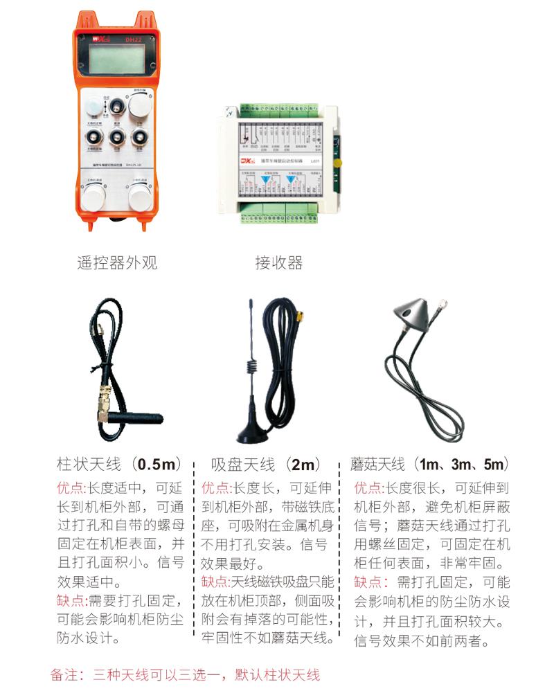
5.Product accessories diagram
6.Product Installation Guide
6.1Product installation steps
6.1Product installation steps
1.Install the receiver in the electric cabinet through the snap-on on the back,Or install it in the electrical cabinet through the screw holes at the four corners of the receiver.。
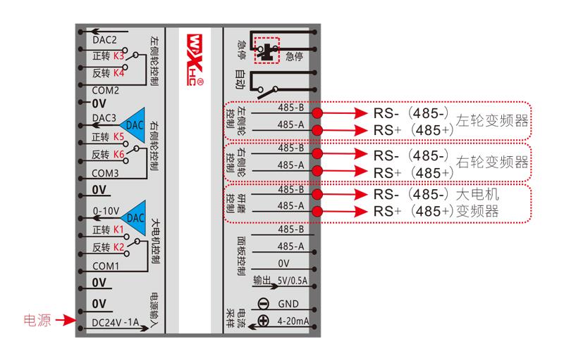
2.Refer to our receiver wiring diagram,Compare your on-site equipment,Connect the device to the receiver via wires。
3.After the receiver is fixed,The antenna equipped with the receiver must be connected,And install the outer end of the antenna or place it outside the electric cabinet,It is recommended to place the signal on the top of the electric cabinet.,It is not allowed to disconnect the antenna,or will
The antenna is placed inside the electrical cabinet,It may cause the signal to be unusable。
4.Finally, install the batteries in the remote control,Tighten the battery cover,Then turn on the remote control power switch,The remote control display will show the normal working interface.,You can perform remote control operation。
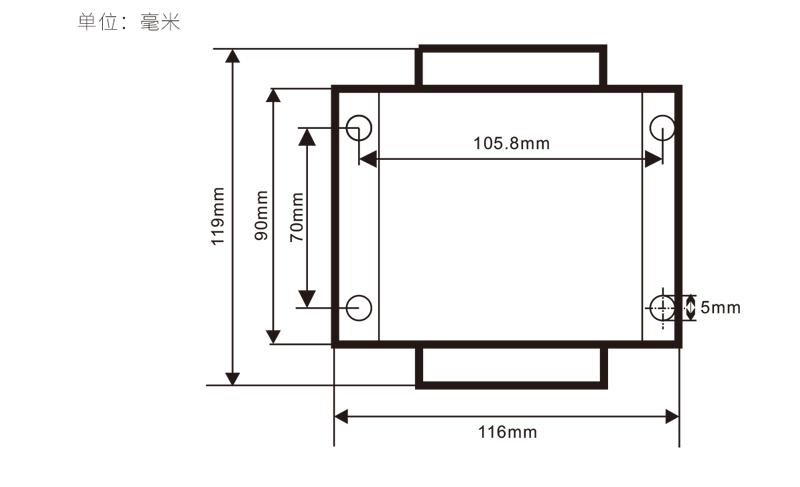
6.2Receiver installation size
6.3Receiver Wiring Reference Diagram
7.Product operating instructions
7.1Remote control parameter settings
Enter the remote control background parameter method:Move the mode switch to manual mode,The speed of the small motor is adjusted to 25 on the left and right,Or both are 0、10、20、40、50,Pull the forward rotation switch of the large motor upward 3 times in a row,Pull down 3 times in succession;
Use the "Small Motor Speed Adjustment" knob to turn pages,After pressing enable, turn the small motor speed control knob to modify the parameters.;
After modification,Turn the page to the end,Select Save and Exit,Press the enable button to exit the menu;
The parameters are as follows:
Maximum current:Large motor current feedback value range,Setting range 15-200A,Default 100;
Speed regulation parameters:Automatic mode small motor automatically accelerates speed,The smaller, the faster,Setting range 200-1500,Default 800;
Deceleration parameters:Set the upper limit for allowed motor speed changes,When the current change exceeds this value,will slow down。
The smaller,The left and right motors decelerate faster,Range 05-12,Default 06;
Acceleration a1:The larger the motor, the faster the speed increases.,Range 00-06,Default 01;
Deceleration a2:The larger the motor speed is, the faster it will decrease.,Range 00-06,Default 02;
Enable speed adjustment:Is it necessary to press Enable to adjust the speed of small motors?,00Disable,01enable,Default 01;
Start self-locking:Will the large motor automatically maintain self-locking after the forward and reverse switch is released?,00do not maintain,01Keep,Default 01;
Maximum walking:Maximum speed of left and right motors,Range 10-100,Default 50;
Cutting current:Maximum cutting current,The screen displays the IC value,Range 15-160,Default 30,Screen corresponding display IC:30。The upper limit of this parameter = maximum current x80%;
Default speed limit:The default small motor automatic cutting speed at startup,Range 00-100,Default 10,The screen correspondingly displays F1.0,This parameter is only accurate when the maximum walk is set to 50。
Automatic mode:Set to 00,Auto/manual switch is a mode switch,Set to 01,Turn the automatic/manual switch to the automatic position,Display display lighting,Automatic terminal output closure on receiver,Hit manual,Automatic output terminal disconnection;
Speed limit offset:Small motor automatic cutting speed upper limit,Range 00-200,Default 60,The screen corresponds to display 6.0;Display value upper limit = speed limit offset × 0.1;
Maximum host:Maximum speed of large motor,Range 10-100,Default 50;
mbus device (required):Large motor inverter model selection,Range 00-03,Default 03;
00-Shanghai Xielin 01-Fuji
02-INVT 03-Huichuan (Zhongchen、Robin Kang)
sbus device (required):Small motor inverter model selection,Range 00-05,Default 03;
00-Shanghai Xielin 01-Fuji
02-INVT 03-Huichuan (Zhongchen、Robin Kang)
04-Yaskawa Da 05-None
7.2Frequency converter parameter setting
1.Command source selection:Communication command channel
2.Main frequency source selection:communication given
3.baud rate:19200
4.Data format:No checksum,Data format<8-N-1>
5.Local address:Left frequency converter is set to 1,The right frequency converter is set to 2,Large motor inverter is set to 3
7.3Remote control operating instructions
1.The machine is powered,Remote control turned on,Enter the remote control background,Set the background parameters of the remote control,main
It is to set the inverter models of small motors and large motors (skip this step if the machine manufacturer has set it);
2.Set the inverter parameters (skip this step if the machine manufacturer has set them);
3.Switch the remote control to manual mode,Then use the remote control to move the machine to the working position;
4.In manual mode,Set the large motor cutting current setting value IC,Set the maximum motor speed;
5.Switch to automatic mode,Set the small motor cutting speed limit F value;
6.In automatic mode,Turn the big motor switch to forward to start the big motor,Then turn the small motor switch to
Forward or reverse gear,The remote control enters automatic cutting mode,Start cutting。
8.Product troubleshooting
| Fault situation | Possible Cause |
Troubleshooting Methods
|
|
Press the power switch,
Cannot turn on and off,
The display does not light up
|
1.The battery is not installed on the remote control
Or the battery direction is installed incorrectly
2.Insufficient battery power
3.Remote control failure
|
1.Check the battery installation of the remote control
2.Replacement battery
3.Contact the manufacturer to return to the factory for maintenance
|
|
Remote control turned on,
Shows network outage and emergency stop!
Please try again!
|
1.The receiver is not powered
2.Receiver antenna not installed
3.The distance between the remote control and the machine is too far
4.Environmental interference
5.Before turning on the remote control,The receiver must be powered on first,Turn on the remote control again
|
1.Check the receiver power on
2.Install the receiver antenna,Install the outer end of the antenna outside the electric cabinet to fix it
3.Operation at normal distance
4.① Optimize the wiring of the electric cabinet,Keep the receiver antenna wiring as far away as possible from 220V and above lines. ② Try to use an independent switching power supply for the receiver power supply.,And add power isolation module and magnetic ring to the power cord.,Increase anti-interference ability
|
|
Remote control turned on,show chage battery
|
1.Insufficient battery power
2.Battery installation or poor contact
|
1.Replacement battery
2.Check battery installation,And whether the metal sheets at both ends of the battery compartment are clean and free of foreign matter,Clean it
|
|
Some buttons on the remote control
Or the switch does not respond
|
1.Switch damage failure
2.Receiver damage fault
|
1.Observe when flipping the switch,Is there a corresponding arrow on the display screen?;There is an arrow displayed,Indicates that the switch is normal;No arrow displayed means the switch is broken.,Return to factory maintenance
2.Return to factory maintenance
|
|
After the receiver is powered on,No light on the receiver
|
1.Power supply abnormality
2.Power wiring error
3.Receiver failure
|
1.Check if the power supply has voltage,Does the voltage meet the requirements
2.Check whether the positive and negative poles of the power supply are connected in reverse
3.Return to factory maintenance
|
9.Maintenance and care
1.Please at room temperature and pressure,Used in dry environments,Extend service life。
2.Please avoid getting wet in the rain、Used in abnormal environments such as blisters,Extend service life。
3.Please keep the battery compartment and metal shrapnel area clean。
4.Please avoid squeezing and dropping the remote control, which may cause damage.。
5.Not used for a long time,Please remove the battery,And store the remote control and battery in a clean and safe place。
6.Pay attention to moisture-proof and shock-proof during storage and transportation。
10.safety information
1.Please read the instructions for use in detail before use,Non-professional personnel are prohibited。
2.Please replace the battery in time when the battery is too low,Avoid errors caused by insufficient battery power causing the remote control to be inoperable.。
4.If repair is required,Please contact the manufacturer,If damage caused by self-repair,The manufacturer will not provide a warranty。